It has been 7 years (!) since I posted my PIC18F2550 KS0108 Graphical LCD Oscilloscope code and schematics. I have long since taken the circuit apart, sold my PIC microcontrollers, and moved on in my life (as one can surmise from my most recent posts detailing my graduate and postdoctoral work). However, I still get inquiries about the Microchip PIC oscilloscope, so I decided to recreate it using a simpler setup using my Arduino Fio.

Here’s a short teaser video just to show that, yes, it works (going through a couple different sine wave frequencies, some random noise, etc. just to illustrate it working):
Click through the break to get more information on the setup.
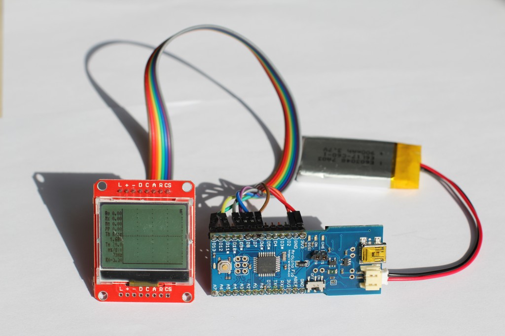
I used an Arduino Fio board that I picked up from SparkFun.com (available at Amazon.com) and a small SPI graphical LCD board that I picked up for a few bucks at dx.com (SKU 153821, also apparently available at Amazon.com). Since I don’t have a soldering iron here, I had to improvise with some female to female cables, also purchased from dx.com (SKU 151650).
Dx.com describes the LCD as a 5V module, but the GLCD board designer’s page (mini12864) states otherwise (translated from Chinese via Google Translate):
Dimensions (L × W × H): 47mm × 38mm × 6mm (excluding pins)
LCD sight (L × W): 33.7mm × 33.5mm
LCD Active Display Area (L × W): 30.7mm × 23mm
Backlight: White LED backlight bracket
Operating voltage: 3.3V ~ 5.5V (built-in booster circuit, without pressure)
Control IC: UC1701
Display format: 128 × 64 rows
Display: Blue on White
So, I ordered one of the graphical LCDs, waited a few weeks for delivery (because dx.com is a notoriously slow shipper), received it, hooked it up, and tried out the following simple “Hello World” script to confirm that that the GLCD/FIO combo functioned:
And it worked!
Thankfully, the code I previously posted was written in C, so porting to the Arduino took only a few minutes. I took advantage of a great open source graphical LCD library (u8glib) to handle the brunt of the work and added a serial port menu for manipulating the various display parameters. One important difference between this project and the previous one: Since the Arduino Fio is a 3.3V device, it can only handle 0-3.3V inputs, limiting its utility as an “oscilloscope” without proper input protection/voltage scaling. However, the code is extremely portable, meaning that you should be able to program any other Arduino and have it up-and-running in no time.
Here’s another 2 videos of the oscilloscope in action:
And finally, here’s the Arduino sketch for the oscilloscope:
Here’s the Arduino sketch for the square wave generator shown in the second video: