As usually, I have been very sporadic in posting new/updated projects due to my prioritization of my doctoral work (i.e., not much time for fun little electronics projects!). However, I’ve been playing around with the Arduino Fio (available from Amazon.com) in my free time for a little while now, so I wanted to post some notes on a very low power usage setup that I was able to put together.
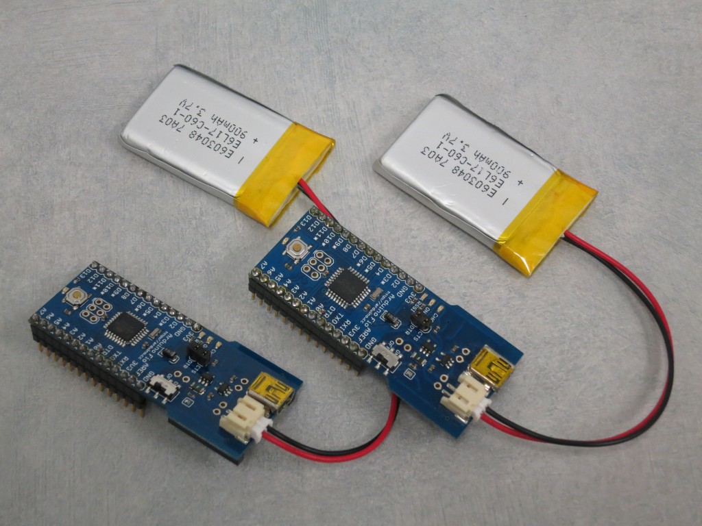
As my free hobby time has dwindled, so has the time I’ve been able to devote to debugging programs written for my little Microchip PICs. So, given my limited time, I decided to dive right into Arduinos — which utilize a higher-level programming language, making things a little quicker and easier for me to tinker — and try to get some wireless communication working. After looking through the possibilities, I settled on the Arduino Fio. The Arduino Fio is a great little Arduino-compatible board that includes a socket for an XBee 802.15.4 wireless module along with a LiPo plug and charger circuit.
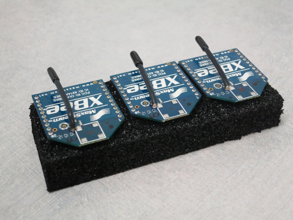
I picked up a pair of Arduino Fios from sparkfun.com (my older revision was recently updated with a newer battery charging IC), along with an XBee Explorer USB (to directly interface/program the XBee modules with my desktop computer) and 3 XBee XB24-AWI-001 modules (XBee 802.15.4 low-power modules with wire antennas).
I may go into a bit more “nitty-gritty detail” for this post, but this is partially because I wanted to recreate all of the steps for this blog post (since I actually last worked on this about a year ago). After receiving all of the components in the mail, I first updated XBee firmware using X-CTU to 17ED using the firmware image from digi.com, xb24_15_4_10ed.zip (available here: ftp://ftp1.digi.com/support/firmware/update/xbee/). Digi has some firmware upgrade instructions that spell everything out.
After pressing “Restore” in X-CTU, the baud rate is reverted to 9600. BD (Interface Data Rate) needed to be changed from “3 – 9600” to “6 – 57600” for use with the Arduino Fio. Selecting “Always update firmware” and pressing “Write” updated the firmware and adjusted the baud rate.
I initially setup the programming and slave XBee modems using the funnel-1.0-r806 XBeeConfigTool available at http://funnel.cc/Hardware/FIO (direct link to the downloads here, after unzipping, the config tool is in “funnel-1.0-r806\tools\XBeeConfigTool\application.windows64\XBeeConfigTool.exe”). Here are the specific settings for my setup of 3 XBees:
For the coordinator/programming XBee (X-CTU configuration profile):
- Mode: Programming radio
- Baud rate: 57600
- PAN ID (The ID of the network these two devices will share) = 8484
- MY ID (The unique ID of the device on the PAN network) = 0000
- DL ID (Destination Address, FFFF means broadcast to all) = FFFF
For the XBee slave 1 (X-CTU configuration profile):
- Mode: Arduino Fio radio
- Baud rate: 57600
- PAN ID (The ID of the network these two devices will share) = 8484
- MY ID (The unique ID of the device on the PAN network) = 0001
- DL ID (Destination Address, 0000 means send only to coordinator radio) = 0000
For the XBee slave 2 (X-CTU configuration profile):
- Mode: Arduino Fio radio
- Baud rate: 57600
- PAN ID (The ID of the network these two devices will share) = 8484
- MY ID (The unique ID of the device on the PAN network) = 0002
In order to use the XBEEs in low-power pin-controlled sleep mode, go into X-CTU and set SM (Sleep Mode) to “1 – PIN HIBERNATE”. Here’s the relevant information from the XBee datasheet:
Pin Hibernate (SM = 1)
- Pin/Host-controlled
- Typical power-down current: < 10 µA (@3.0 VCC)
- Wake-up time: 13.2 msec
Pin Hibernate Mode minimizes quiescent power (power consumed when in a state of rest or inactivity). This mode is voltage level-activated; when Sleep_RQ (pin 9) is asserted, the module will
finish any transmit, receive or association activities, enter Idle Mode, and then enter a state of
sleep. The module will not respond to either serial or RF activity while in pin sleep.To wake a sleeping module operating in Pin Hibernate Mode, de-assert Sleep_RQ (pin 9). The
module will wake when Sleep_RQ is de-asserted and is ready to transmit or receive when the CTS
line is low. When waking the module, the pin must be de-asserted at least two ‘byte times’ after
CTS goes low. This assures that there is time for the data to enter the DI buffer.
In addition, D3 (DIO3 Configuration) to “5 – DO HIGH” and IU (I/O Output Enable) to “0 – DISABLED”. I’ve attached the X-CTU configuration profiles for each of the XBees above. Now… onto the Arduino!
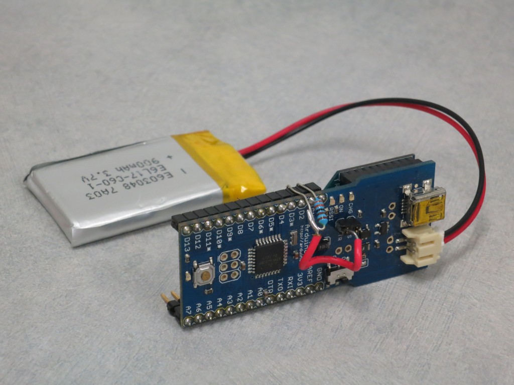
The DTR line on the Ardunio FIO is connected to pin 9 on the XBee (Sleep_RQ), so in order to take advantage of the pin hibernation, it needs to be pulled to ground and tied to the Arduino FIO D2 to control the XBee’s hibernation. I soldered a header onto the CTS and DTR pins on the FIO, connected D2 to DTR using a wire and pulled the line to ground using a resistor:
Finally, I took advantage of the Ardunio power-save sleep mode of the ATmega328P to lower the power usage further (see the ATmega328P datasheet). Here is some barebones code, where the Arduino puts the radio to sleep and wakes up every 8 seconds, checks if the timekeeper variable has hit 8, and, if so, transmits an increasing variable (MeasurementID). Basically, MeasurementID is transmitted every approximately 64 seconds.


