 A friend at Purdue University (Sumanth Peddamatham) helped motivate and inspire me to create a high voltage flyback transformer driver for a computer CRT flyback transformer. While the schematic and code for driving the transformer are extremely straightforward and simple, finding and obtaining a high quality solid state flyback transformer can be difficult. Please note that the voltages generated by the flyback transformer are potentially very dangerous, so extreme care must be exercised when building and/or using the schematic presented in this project. Diode split flyback transformers (like the one used in this project) can output 25kV or more.
Disclaimer: The high voltage devices and schematics presented on this website () and the pages herein are for educational and experimental purposes only. Build and/or use at your own risk. I cannot be held liable or responsible and will not accept any type of liability in any event, in case of injury, damage to persons or property, or even death by building and/or using this device or any other high voltage device posted on this website. By accessing, reading, and/or printing the articles presented here you agree to be solely responsible and exempt me from any criminal and/or lability charges and/or suits. Please note that safety is the primary concern when working with high voltage circuits. Always be careful, use extreme caution with high voltage circuits, and play it safe!
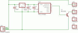
Here is the full schematic for the driver. Yes, it is this simple. All that is needed is a power supply (preferably >9V), a 7805 +5V linear voltage regulator, decoupling capacitors (C1, C2, & C3), a PIC12F683, a suitable logic level power MOSFET (I used an IRL530), and a flyback transformer. It is important to note that the MOSFET needs to be heatsinked, otherwise it could overheat.
JP2 (FBPriP) is the positive input of the primary winding, JP3 (FBPriG) is the ground/negative input of the primary winding, and JP4 (FBSecP) and JP5 (FBSecG) are the positive and negative outputs of the secondary winding where the high voltage is generated.
The flyback transformer was found in a broken 21″ CRT monitor. An alternative to opening a CRT and exposing yourself to potentially harmful voltages is to purchase a replacement flyback transformer from a surplus store or from eBay. I experimented with the driving frequency to find the optimal output and found that 20kHz produced the longest arcs for this flyback transformer.
As always, please feel free to contact me if you have any questions about the setup and as the disclaimer above says: Always be careful, use extreme caution with high voltage circuits, and play it safe!
Source Code
This is the source code for the driver. Please note that the driving frequency can be adjusted by changing the following line:
delay_us(25);
Videos
Here are three videos of the PIC12F683 High Voltage Flyback Transformer Driver in action. The first video demonstrates the high voltage arcing through a beercap-ful of beer (Stella Artois) with a power supply voltage of 9V. The second video demonstrates the high voltage arcing through a cap-ful of rum (Sailor Jerry) with a 24V supply voltage. The third video demonstrates the high voltage arcing through a cap-ful of pancake syrup with a 24V supply voltage.
Pictures
Here are a couple of pictures from experimenting with the driver:


