 Using the PIC18F2550 GLCD Text Test as a basis for further experimentation, I put together a simple and accurate graphical oscilloscope using a PIC18F2550 microcontroller and a AGM1264F graphical LCD. The oscilloscope measures the average voltage, the maximum voltage, the minimum voltage, the peak-to-peak voltage, and the zero-crossing frequency for a DC signal over 100 samples. The oscilloscope has a built in edge trigger function that can be set to capture on rise or fall (or disabled altogether). The time scale for the display is variable and can be easily redefined using the changeTimeDivision function. Likewise, the voltage range can be change to 0-5V, 0-2.5V, and 0-1.25V. The main limitations of this oscilloscope include relatively slow acquisition time and sampling rate (~60kHz) and the fact that the inputs are limited by the constraints of the internal ADC. However, it is a very nice display and I highly suggest you view the videos to see it in action.
Full Circuit
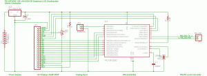
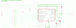
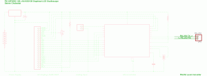
The source and firmware for the circuit can be found at the bottom of the page. Each section of the circuit is labeled in the schematic. All of the sections and their components are described and discussed below. The part numbers for the components are linked to websites for data and more information when available.
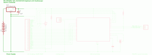
Power Supply
The power supply uses a 9 volt battery and a TC1262-5.0V high-accuracy low-dropout linear voltage regulator to provide a stable 5 volt supply for the microcontroller and the graphical LCD. A 1uF (microFarad) polarized decoupling capacitor is necessary on the output of the voltage regulator to prevent power spikes or ripples. A wall wart power supply as low as 5.3V can be substituted for the 9 Volt battery.
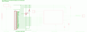
AZ Displays AGM1264F
The AGM1264F is 128 x 64 pixel graphical LCD with built in controllers that allow is to be easily controlled using a PIC microcontroller. It is a 128 x 64 pixel graphical LCD and has an LED backlight, onboard negative voltage generator (LMC7660) for LCD driving, onboard Samsung KS0108 controller, and an 8-Bit MPU interface.
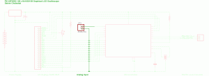
Analog Input
The 1st analog input (Pin A0) is configured to be an analog input. Please note that “The source impedance affects the offset voltage at the analog input (due to pin leakage current). The maximum recommended impedance for analog sources is 2.5 kΩ.” (PIC18F2550, p.260)
Microcontroller
The microcontroller used is a Microchip PIC18F2550. I modified the PIC18F2550 Tiny PIC Bootloader assembly file so I could use a 20MHz crystal/resonator at 115,200 baud (the modified bootloader can be found at the bottom of the page). The PIC18F2550 runs at 48MHz using the internal PLL. R1 is a pull-up resistor necessary for operation. C1 is a stabilizing capacitor that is used for the onboard USB voltage regulator, which is not used in this project. The component marked ‘RES’ is a 20MHz resonator.
RS232 Level Converter
The microcontroller USART pins need to be connected to a RS-232 Level Converter to connect to a PC for firmware updates using the Tiny PIC Bootloader. Otherwise, after initial programming they can be left disconnected.
Source and Firmware
The PIC must initially programmed with the ‘SAC_tinybld18F2550usb _20MHz_115200_48MHz’ hex file to program the bootloader on the PIC. Then, using Tiny PIC Bootloader, the hex file can be placed on the chip using the Tiny PIC Bootloader frontend with ’12h 34h 56h 78h 90h’ in the ‘List of codes to send first:’ in the ‘Options’ menu. Please feel free to contact me if you have any problems.
- SAC_tinybld18F2550usb_20MHz_115200_48MHz.hex
- 18F2550 GLCD Oscilloscope DR1r1.c (hex)
- GLCD – modified.c
Videos
Here are three videos of the PIC18F2550 GLCD Oscilloscope in action. The first video demonstrates sine, triangle, and square waves of different frequencies. The second video demonstrates different waves with shifting amplitudes and offsets. The third video compares the display of the PIC18F2550 GLCD Oscilloscope to the display of a Hewlett Packard 54603B oscilloscope.
Update (November 15, 2006)
Here is the firmware without the bootloader code:
Update (February 1, 2007)
Here is untested firmware for the PIC18F4550 without the bootloader code:
Update (April 11, 2007)
Here is untested firmware for the PIC18F252 and PIC18F452 without the bootloader code. Please note that you will need to use a 10MHz crystal/resonator instead of a 20MHz one.
