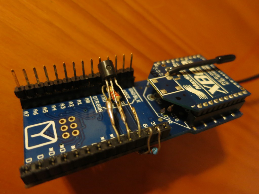
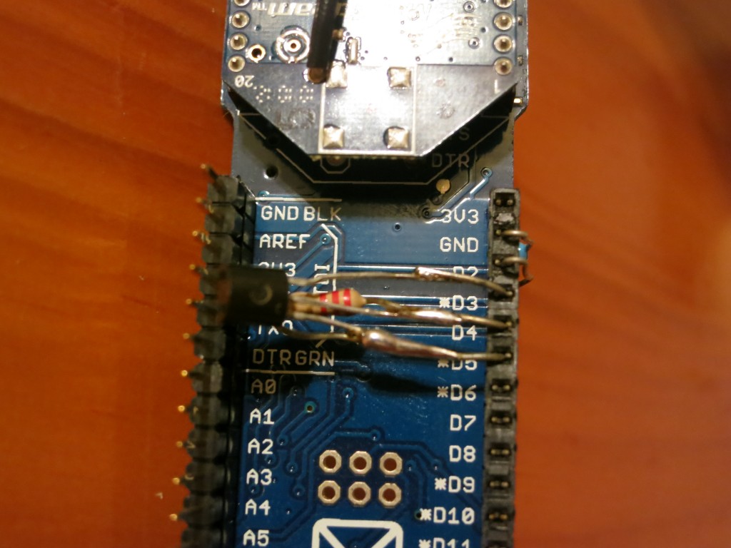
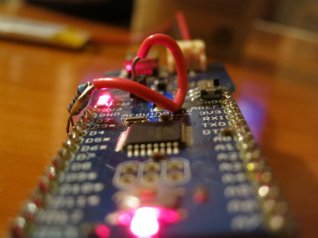
We have a Arduino Fio temperature logger, so now maybe we can increase the accuracy by adding an external temperature sensor. I have a couple of DS18B20 Programmable Resolution 1-Wire Digital Thermometers, so I thought, heck, let’s try one out!
These temperature sensors are much more accurate out-of-the-box, so I don’t need to deal with calibration (which I did need to worry about with the internal thermometer). In addition, using separate, discrete components allows for the possibility of putting temperature sensors directly on/in whatever you may want to measure (rather than merely measuring the ambient temperature) and the potential for multiple temperature sensors with a single Arduino Fio (which are available at Amazon.com).
So, the most important addition is the Arduino OneWire.h library. Once we have that, all that’s needed is two simple declarations:
[code lang=”arduino”]
#include <OneWire.h> // Get here: http://www.arduino.cc/playground/Learning/OneWire
OneWire ds(DS18B20Data);
[/code]
And a modified readTemp function:
[code lang=”arduino”]
// See: http://www.arduino.cc/playground/Learning/OneWire
float readTempDS18B20() {
int HighByte, LowByte, TReading, SignBit, Tc_100;
byte i;
byte present = 0;
byte data[12];
byte addr[8];
float resultTempFloat;
digitalWrite(DS18B20Power,HIGH); // Power up the DS18B20
delay(250);
ds.search(addr);
if ( OneWire::crc8( addr, 7) != addr[7]) {
return 0.0; // CRC is not valid!
}
ds.reset();
ds.select(addr);
ds.write(0x44,1); // Start conversion, with parasite power on at the end
delay(1000); // Maybe 750ms is enough, maybe not
// We might do a ds.depower() here,
// but the reset will take care of it.
present = ds.reset();
ds.select(addr);
ds.write(0xBE); // Read Scratchpad
for ( i = 0; i < 9; i++) { // we need 9 bytes
data[i] = ds.read();
}
LowByte = data[0];
HighByte = data[1];
TReading = (HighByte << 8) + LowByte;
SignBit = TReading & 0x8000; // Test most sig bit
if (SignBit) // Negative
{
TReading = (TReading ^ 0xffff) + 1; // Take 2’s comp
}
ds.reset_search();
digitalWrite(DS18B20Power,LOW); // Turn off DS18B20
resultTempFloat = (float) (6 * TReading) + TReading / 4; // Multiply by (100 * 0.0625) or 6.25
resultTempFloat = resultTempFloat/100;
resultTempFloat = resultTempFloat * 1.8 + 32.0; // Convert to F
return resultTempFloat;
}
[/code]
And we are ready to read! Note that the measurement times are a bit longer (I measured ~75 seconds in between transmissions) because of the 1 second settling time for the DS18B20. Here is some example output from TeraTerm (I measured the ambient temperature for measurements 1-10, then put my thumb onto the DS18B20 for measurements 11 & 12, and then allowed the DS18B20 to return to ambient for readings 13-20):
[code gutter=”false”]
ƒƒª 0 0 0
~
Aª 1 3.303 71.70
~
Aª 2 3.303 71.14
~
@ª 3 3.303 71.22
~
@ª 4 3.303 71.07
~
?ª 5 3.303 71.30
~
@ª 6 3.303 70.95
~
@ª 7 3.303 71.26
~
?ª 8 3.303 71.60
~
?ª 9 3.303 71.35
~
0ª 10 3.303 71.01
~
7ª 11 3.303 77.35
~
6ª 12 3.303 77.35
~
Aª 13 3.303 73.72
~
Aª 14 3.303 72.14
~
Aª 15 3.303 71.66
~
Aª 16 3.303 71.49
~
Aª 17 3.303 71.27
~
Aª 18 3.303 71.40
~
Aª 19 3.303 71.23
~
Aª 20 3.303 70.91
[/code]
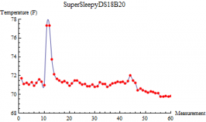
I stored the data for another 40 readings, cut out all of the trash data between the carriage returns (deliminating the readings) and sync characters (which visually show up as “ª” in TeraTerm), removed the initial sync reading, and plotted the temperature data in Mathematica (voltage was constant):
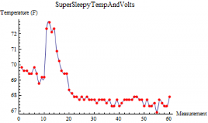
Compare to the temperature results of the Arduino Fio internal temperature sensor:
Here’s all of the Arduino Fio SuperSleepyDS18B20 code:
[code lang=”arduino”]
/*
* SuperSleepyDS18B20 SuperSleepyDS18B20.ino
* Steven A Cholewiak – www.semifluid.com
*
* This sketch takes advantage of the XBee’s hibernation mode as
* well as the Ardunio Fio’s Power Save Mode to grossly reduce power
* consumption. It impliments a temperature logging IC (DS18B20)
* That has been connected to D3,D4,D5. Provides a much more
* accurate temperature measurement than the internal thermometer
* (see SuperSleepyTempAndVolts.ino).
*
*/
#include <avr/wdt.h>
#include <avr/sleep.h>
#include <avr/interrupt.h>
#include <OneWire.h> // Get here: http://www.arduino.cc/playground/Learning/OneWire
const int ledPin = 13;
const int DS18B20Ground = 3; // DS18B20 Pin 1
const int DS18B20Data = 4; // DS18B20 Pin 2 NOTE: 4.7k pull-up resistor required between data and power
const int DS18B20Power = 5; // DS18B20 Pin 3
const int XBeeSleep = 2; // Connect to XBee DTR
const int waitPeriod = 8; // Number of 8 second cycles before waking
// up XBee and sending data (8*8 = 64 seconds)
OneWire ds(DS18B20Data); // Setup DS18S20 Temperature chip I/O
// See: http://code.google.com/p/tinkerit/wiki/SecretVoltmeter
float readVcc() {
signed long resultVcc;
float resultVccFloat;
// Read 1.1V reference against AVcc
ADMUX = _BV(REFS0) | _BV(MUX3) | _BV(MUX2) | _BV(MUX1);
delay(10); // Wait for Vref to settle
ADCSRA |= _BV(ADSC); // Convert
while (bit_is_set(ADCSRA,ADSC));
resultVcc = ADCL;
resultVcc |= ADCH<<8;
resultVcc = 1126400L / resultVcc; // Back-calculate AVcc in mV
resultVccFloat = (float) resultVcc / 1000.0; // Convert to Float
return resultVccFloat;
}
// See: http://www.arduino.cc/playground/Learning/OneWire
float readTempDS18B20() {
int HighByte, LowByte, TReading, SignBit, Tc_100;
byte i;
byte present = 0;
byte data[12];
byte addr[8];
float resultTempFloat;
digitalWrite(DS18B20Power,HIGH); // Power up the DS18B20
delay(250);
ds.search(addr);
if ( OneWire::crc8( addr, 7) != addr[7]) {
return 0.0; // CRC is not valid!
}
ds.reset();
ds.select(addr);
ds.write(0x44,1); // Start conversion, with parasite power on at the end
delay(1000); // Maybe 750ms is enough, maybe not
// We might do a ds.depower() here,
// but the reset will take care of it.
present = ds.reset();
ds.select(addr);
ds.write(0xBE); // Read Scratchpad
for ( i = 0; i < 9; i++) { // we need 9 bytes
data[i] = ds.read();
}
LowByte = data[0];
HighByte = data[1];
TReading = (HighByte << 8) + LowByte;
SignBit = TReading & 0x8000; // Test most sig bit
if (SignBit) // Negative
{
TReading = (TReading ^ 0xffff) + 1; // Take 2’s comp
}
ds.reset_search();
digitalWrite(DS18B20Power,LOW); // Turn off DS18B20
resultTempFloat = (float) (6 * TReading) + TReading / 4; // Multiply by (100 * 0.0625) or 6.25
resultTempFloat = resultTempFloat/100;
resultTempFloat = resultTempFloat * 1.8 + 32.0; // Convert to F
return resultTempFloat;
}
void sleepNow()
{
/* Now is the time to set the sleep mode. In the Atmega8 datasheet
* http://www.atmel.com/dyn/resources/prod_documents/doc2486.pdf on page 35
* there is a list of sleep modes which explains which clocks and
* wake up sources are available in which sleep modus.
*
* In the avr/sleep.h file, the call names of these sleep modus are to be found:
*
* The 5 different modes are:
* SLEEP_MODE_IDLE -the least power savings
* SLEEP_MODE_ADC
* SLEEP_MODE_PWR_SAVE
* SLEEP_MODE_STANDBY
* SLEEP_MODE_PWR_DOWN -the most power savings
*
* the power reduction management <avr/power.h> is described in
* http://www.nongnu.org/avr-libc/user-manual/group__avr__power.html
*/
set_sleep_mode(SLEEP_MODE_PWR_SAVE); // Sleep mode is set here
sleep_enable(); // Enables the sleep bit in the mcucr register
// so sleep is possible. just a safety pin
sleep_mode(); // Here the device is actually put to sleep!!
// THE PROGRAM CONTINUES FROM HERE AFTER WAKING UP
sleep_disable(); // Dirst thing after waking from sleep:
// disable sleep…
}
ISR (WDT_vect) { // WDT Wakeup
cli();
wdt_disable();
sei();
}
// Variable Definition
volatile int MeasurementID = 1;
volatile int timeKeeper = 0;
volatile float averageVcc = 0.0;
volatile float averageTemp = 0.0;
void setup(void) {
Serial.begin(57600);
pinMode(DS18B20Ground, OUTPUT);
digitalWrite(DS18B20Ground, 0); // Ground the DS18B20 GND pin
pinMode(XBeeSleep, OUTPUT);
digitalWrite(XBeeSleep, 0); // Enable XBee
digitalWrite(ledPin, 1); // Turn on Notification LED
delay(4000); // 4 second LED blink, good for wireless programming
digitalWrite(ledPin, 0); // Turn off Notification LED
Serial.write( 170 ); // Sync Byte
Serial.print( ‘\t’ ); // Tab
Serial.print( ‘0’ ); // Reading # (0)
Serial.print( ‘\t’ ); // Tab
Serial.print( ‘0’ ); // Voltage (unmeasured, so 0)
Serial.print( ‘\t’ ); // Tab
Serial.println( ‘0’ ); // Temperature (unmeasured, so 0)
digitalWrite(XBeeSleep, 1); // Disable XBee
}
void loop(void) {
averageVcc = averageVcc + (float) readVcc();
averageTemp = averageTemp + (float) readTempDS18B20();
if (timeKeeper == (waitPeriod-1)) { // Transmit every 8*8 (64) seconds
digitalWrite(XBeeSleep, 0); // Enable XBee
delay(50); // Wait for XBee Wakeup
Serial.write( 170 );               // Sync Byte
Serial.print( '\t' );
Serial.print( MeasurementID, DEC );
Serial.print( '\t' );
Serial.print( (float) (averageVcc/waitPeriod) , 3);
Serial.print( '\t' );
Serial.println( (float) (averageTemp/waitPeriod) , 2);
MeasurementID++;

digitalWrite(ledPin, 1);           // Turn on Notification LED
delay(50);                         // Blink LED
digitalWrite(ledPin, 0);           // Turn off Notification LED

digitalWrite(XBeeSleep, 1);        // Disable XBee

averageVcc = 0;                    // Reset voltage for new measurements
averageTemp = 0;                   // Reset temperature for new measurements
timeKeeper = 0;
} else { // Add a reading to the average
digitalWrite(ledPin, 1); // Turn on Notification LED
delay(1); // Blink LED very quickly
digitalWrite(ledPin, 0); // Turn off Notification LED
timeKeeper++;
}
wdt_reset(); // Get ready to go to sleep…
watchdogEnable(); // Turn on the watchdog timer
sleepNow(); // Go to sleep, watchdog timer will wake later
}
void watchdogEnable() { // Turn on watchdog timer; interrupt mode every 8.0s
cli();
MCUSR = 0;
WDTCSR |= B00011000;
//WDTCSR = B01000111; // 2 Second Timeout
//WDTCSR = B01100000; // 4 Second Timeout
WDTCSR = B01100001; // 8 Second Timeout
sei();
}
[/code]
