PIC18F2550 USB HID IO

After completing the PIC18F2550 USB HID Oscilloscope, I decided to expand upon the project and firmware to include multiple analog inputs and digital i/o. The base firmware for this project is the same as the PIC18F2550 USB HID Oscilloscope‘s; however, more features have been added that allow the user to access the PIC18F2550’s Port B for digital i/o. In addition, the firmware now allows the user to access the AN0-AN4 analog pins for monitoring and data acquisition.

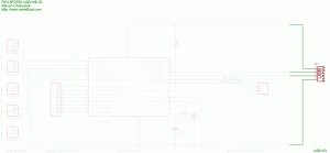
Full Circuit
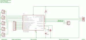
The source and firmware for the circuit can be found at the bottom of the page. Each section of the circuit is labeled in the schematic. All of the sections and their components are described and discussed below. The part numbers for the components are linked to websites for data and more information when available.

Analog Inputs
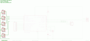
The 5 analog inputs are connected to pins A0, A1, A2, A3, and A5, which are configured to be analog inputs. Please note that “The source impedance affects the offset voltage at the analog input (due to pin leakage current). The maximum recommended impedance for analog sources is 2.5 kOhms.” (PIC18F2550, p.260)

Digital Inputs/Outputs
The digital inputs and outputs share Port B. Please note that:
Maximum output current sunk by any I/O pin = 25 mA
Maximum output current sourced by any I/O pin = 25 mA
Maximum current sunk by all ports = 200 mA
Maximum current sourced by all ports = 200 mA

Microcontroller
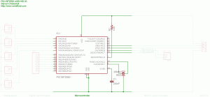
The microcontroller used is a Microchip PIC18F2550. I modified the PIC18F2550 Tiny PIC Bootloader assembly file so I could use a 20MHz crystal/resonator at 115,200 baud (the modified bootloader can be found at the bottom of the page). The PIC18F2550 runs at 48MHz using the internal PLL. R1 is a pull-up resistor necessary for operation. C1 is a stabilizing capacitor that is used for the onboard USB voltage regulator, which is used in this project. The component marked ‘RES’ is a 20MHz resonator.

RS232 Level Converter
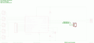
The microcontroller USART pins need to be connected to a RS-232 Level Converter to connect to a PC for firmware updates using the Tiny PIC Bootloader. Otherwise, after initial programming they can be left disconnected.

USB I/O
The PIC is connected to the computer through a USB port and is bus-powered.

Source and Firmware
The PIC must initially programmed with the ‘SAC_tinybld18F2550usb _20MHz_115200_48MHz’ hex file to program the bootloader on the PIC. Then, using Tiny PIC Bootloader, the hex file can be placed on the chip using the Tiny PIC Bootloader frontend with ’12h 34h 56h 78h 90h’ in the ‘List of codes to send first:’ in the ‘Options’ menu. Please feel free to contact me if you have any problems.

Update (November 15, 2006)
Here is the firmware without the bootloader code:

Update 2 (December 18, 2006)
Here are untested PIC18F4550 firmwares:

90 thoughts to “PIC18F2550 USB HID IO”

  1. Hi
    Looks a very nice code.
    So could you send me the full code for this i/o in C for Pic18f4550 so i can study as I am learning PICs, but without boot loader .
    Thanks
    Carlos Palma

  2. Hi steve
    Thanks for the code but still couldnt put it working.I use de MCC18 compiler and i get errors.
    I think still files missing. So can you help me sending me all the files in a zip mode.
    Thanks a lot
    Carlos Palma

  3. Hi steve
    At least i can make it working, just change the compiler.
    But stops a lot of times i will study it better than i will tell you about my evolution.
    Any away have you some other code than make the ADC read more in real time, i mean faster with out stoping.
    TKS
    Carlos Palma

  4. Hi Maurizio.
    I have used de CCS PCWH compiler and works but i have to coment 3 lines of code. The VB6 stops lot of times i dont know why yet.

  5. Carlos: I use CCS PCWH 3.249. The compiler provides a number of built-in USB functions and header files, which are likely the files that you are missing. Due to copyright restrictions I cannot share the source code for these header files. I look forward to hearing how you modified the source code. The PIC captures in storage mode (to RAM) to facilitate fast and reliable measurements. You can do real-time measurements by repeatedly sending the usbReadADC HID instruction.

    Maurizio: As I said to Carlos, I use CCS PCWH 3.249. Which three lines of code do you have to comment out? For non-bootloader operation I comment out:
    #build(reset=0x1, interrupt=0x8) // Necessary for Bootloader
    #ORG 0x0F00,0x0FFF {} // Necessary for Bootloader
    Also, if you could send me a message (http://www.semifluid.com/?page_id=6) with the errors that VB6 stops on, I can try to help.

  6. Hi Steve,
    thanks for reply.
    I’m trying to program the host with C# language. I will contact you as soon as I have some good results.

  7. #include //Microchip 18Fxx5x hardware layer for usb.c

    Where can I find this header file in the source code you had provided?

    I’m trying to search everywhere but I still couldn’t find this header file. Please help me and guide me along.

    Thanks.

    Jeff

  8. The includes are included with the CCS libraries. I can’t send or post the files because they are copyrighted. Sorry, buy you will have to compile the source code with a CCS C compiler to take advantage of the USB includes.

  9. can u compile the codes for PIC18F4550 and upload the hex file ?
    i want to try it on my picdem fs usb board.
    i don have ccs compiler, im using Microchip C18.
    thanks !

  10. I’m doing a similar project using the PIC18F4550. I already got the hardware up and running (using the Microchip C18-compiler and the examples from microchip.com). I don’t have access to the CSS-compiler, but I’ll try to port your code to C18. If you have some hints or if you could post a 18F4550-version of the hex I’ll be grateful. I’ll get back to you all, when I have a working sample.

  11. YJ and Rasmus – I’ve attached untested PIC18F4550 code to the post. Please let me know if it works! (I don’t have a PIC18F4550 on-hand to test)

  12. Thank you for doing a 18f4550-version. As far as I can see it works! I used the no-bootload-hex-version.
    I tried with the oscilloscope software as well and it’s all fine. very nice actually 🙂
    I’ll try to port it to the C18-compiler, but I’m not sure if it’s out of my league.

  13. Greetings, Steve!
    All my attempts to start this project also success have not crowned. 🙁
    PIC also it is identified by a computer as the HID-device, descriptors accepts, and with the program of display does not work.
    Program SnoopyPro shows, that after reception of descriptors the stop occurs on 7 and 8 segments (I shall try to result a copy of the report here):
    Seq Direct Endpoint Time Function
    7 ??? down n/a 0.040 BULK_OR_INTERRUPT_TRANSFER –
    URB Header (length: 72)
    SequenceNumber: 7
    Function: 0009 (BULK_OR_INTERRUPT_TRANSFER)
    TransferFlags: 0x00000003
    No TransferBuffer

    8 ??? down n/a 0.040 BULK_OR_INTERRUPT_TRANSFER –
    URB Header (length: 72)
    SequenceNumber: 8
    Function: 0009 (BULK_OR_INTERRUPT_TRANSFER)
    TransferFlags: 0x00000003
    No TransferBuffer

    And attempt to look in PIC at debugging MPLAB ICD2 has shown a course of the program that the code turns not further the operator if (usb_kbhit (1)), on a site:

    set_adc_channel (0);
    delay_ms (1);

    while (TRUE) {
    usb_task ();
    usb_debug_task ();
    if (usb_enumerated ()) {
    if (usb_kbhit (1)) {
    usb_get_packet (1, in_data, 8);

    usb_kbhit () I could not find the description of function neither in files пректа, nor in Help on CCS. Your ideas?
    To make sure, that a problem not of the controller, I have tried one more similar project (HID джойстик, 8 resistors and 12 buttons). 🙂 http://artjoy.narod.ru/ru/index_ru.html
    To you it can be to be very interesting. The truth it on MCC18, but the version for students for 60 days is accessible on site Microchip. I therefrom also have loaded it. And so it was started practically without problems. Only in a configuration has replaced quartz with 4MHz on 20MHz.
    Almost ready 8-channel oscillograph with controls! To tell the truth, a site Russian-speaking, but comments in software in English.
    P.S. In general for me there is not clear your choice. Devices HID by definition slow – 800 bytes per one second.The virtual COM-port is much faster, and functionality you not теряшь, and examples of such realization at Microchip too are.
    Yours faithfully, Andrey. Moscow.

  14. Steve, and can try or in your project to substitute descriptors from joystik, or in his(its) project your descriptors? At me while it, I am afraid will fail. Many mistakes I shall do… Or it is not interesting to you in such variant?
    Yours faithfully, Andrey. Moscow.

  15. Andrey – usb_kbhit() is defined in usb.c It returns true when the endpoint contains data from the USB host. Thank you for pointing me to that other website, it looks very interesting! Another project you might want to look at is the CREATE USB interface. I used the HID descriptor because it does not require drivers. To be honest, this project is slower than I would like. I’m updating the code to use 64-byte packets and have found a significant increase in speed (theoretically this would be 1 64-byte packet every ms, which is 62.5 kilobytes/second). This project could easily be ported to a virtual COM port, but then it would require the COM port driver. I could also change the descriptors to joystick, but I used a custom device type so that it would not interfere with other applications (hopefully!).

  16. Hi Steve, I was wondering if the RS-232 input in the device can be used for serial communications (and not just firmware upgrades) ?

    If so, does the interface support bulk transfer so that I can continuously feed data on the RX pin and read this in the software without missing any data…The input is a 19600 bps data…
    Does the program require modifications ?

  17. #18 (Eric) – Right now the serial port is only used for the bootloader. The code can be easily modified to accept USB or serial input, but I have not done that unfortunately. What it would need is a circular buffer on the serial input and then a loop in main() to process the commands (which is what is currently being done with the USB communication).

    #19 (steve) – I actually have a copy of .Net that I purchased here at Purdue (it’s a steal with the educational discount!), but I have yet to install it. I am living in the past and still using VB 6.0, so I haven’t taken the time to upgrade.

  18. hello PIC ers

    Bravo to steve, great site , and great developments for a complete beginner like me.
    Did you succeed in building a faster working firmware for 4550 than the CUI creat usb interface one ?
    thank you if you can post your last researches, and post the links of eventual new firmware

    Jejobas

  19. Hi
    Looks a very nice code.
    So could you send me the full code for this i/o in C for Pic18f4550 so i can study as I am learning PICs.

  20. hello steve,your applications looks very nice and useful.i have seen this project and i think i will use it for my graduation project, servo control of a pm dc motor via usb port.In the beginning i thought controlling rs 232 port would be more simpler but using usb is more useful specially laptop user like me.i have begun recently i hope you will help me soon to develop.i will send you my schematic as soon as it is ok.

  21. Hi!I am a chinese friend,thanks so much for your article,could you send me the full code for this i/o in C for Pic18f4550 so i can study as I am learning PICs.
    yang

  22. #22, #23 (jignesh), & #25 (yang) – Please see the bottom of the post. I have included code for the PIC18F4550 for you to experiment with. Good luck!

    • 18F4550 USB HID CRC IO.c (hex)
    • 18F4550 USB HID CRC IO – no bootloader.c (hex)

    #24 (sally) – Thank you! I’d love to see how your project turns out!

  23. Hi!!!

    Very cool article, could you help me to my proyect. I need to do a I/O interfase only digitla inputs and outputs, description of the proyect:

    all port A as inputs
    all port B as outputs
    all port C as inputs
    all port D as outputs

    I need the PIC seed the info. of port A to the PC everytime( a gonna put a sensor in the inputs of the port A and C), and depending of the states of port A is gonna be my outputs of port B and D such a turn
    on/off something, can you help me please.

    I need to understand how I can interpretate the informacion the PIC send to me, the configuracion of the I/O of the PIC and how I can
    do to send info. to the states of the inputs everytime to the pc and send info of the pc to the pic to change the states of the outputs

    Edgar E.

  24. Ohhh sorry I confuse PIC18f4550 with PIC18f2550, but always all port A could be all inputs and port B all outputs.

    Could be read port A send the info to the PC, i process the info of port A in the PC and then send the info to the PIC and show in the port B could be turn off/on the pins of port B or put the same states of the pins of port A into the port B but sending info trought the PC.

  25. HI,

    which compiler is being used here??? IS there any way the software can be written in the MPLAB software instead??? DOnt have CSS and cant afford it either…

    Thanks

    Regards
    Joseph

  26. hay can any one tell me code & circuit diagram of 8 input switchs circut diagram
    a circuit which can take 8 diffrent reagings from 8 different switches at the same time and send the data to the ps through the usb port
    Please help
    Please can some one give the the compleate circuit diagram & code of this circuit

    Please HELP

  27. I have one project control and measure pins of pic 18f4550 by using usb . And there is no so much information about it. could you send me the full code for this i/o in C for Pic18f4550 or pic 18f2550 so i can modify for my project

    Thanks & Best Regards
    Ahmet Tiryaki

  28. Hello all, this question is open to anyone. My question is I have the PICDEM FS USB board and it uses the PIC18F4550. I have put the 18F4550 hex with no bootloader on the board. When I run the program it is not responding aka the device is connected, and it says USB Device: Disconnected. Does anyone know what else needs to be done?

  29. Hey Steve,

    I am trying to use your project with my PICDEM FS USB DEMO board and its not working. I kind of know what the problem is. I need to changed the location of where the code starts and ends because my bootloader uses certain sections of memory. To edit the code I need CCS PCH compiler, I assume you already have it. I am trying options besides buying the compiler because I am a hobbyist and its expensive. Is there to use the C18 compiler through MPLAB to compile the c file instead of PCH compiler?

    P.S. This question is open to anyone who knows the answer.

  30. I have built the circuit with the 18F4550, however it does not function properly. The device is detected by the VB app however it does not function when trying to send or receive data. I have looked over the entire device and cannot find what might be the problem.

    Also, for those who have had trouble with the 18F4550, just in case you did not notice, but you can not use the schematic on this page for the 4550, the pin-out is different as the 4550 is a 40 pin device. Look at the 4550 datasheet to get the correct pin numbers to use.

  31. i have made a demo usb board with pic18f4550,then i downloaded firmware from microchip site,which i will program in pic MPLABICD2,but problem is this when i build this project in MPLAB,build is getting failed and telling error some c018i.o file is out of date. plese suggest the solution.
    thanking you
    haresh

  32. I Want to used VB6 Control LED By HScroll Bar in VB6. LED has Bright when Drag Mouse at HScroll Bar on Max Value.and Drag Mouse at HScroll Bar on Low Value LED has low Bright.I dont know to write This source code.Thank you very much for an instruction

  33. Hello Steve,

    I’m interested in Sally’s project regarding USB control of a permanent magnet DC motor (PMDC) – see comment #24. Would you mind passy my e-mail address on to her?

    Thanks,

    Ewan

  34. Hi Steve..
    That’s really cool. Just what I need to start my new “adventure” into USB world. Mind sharing the PIC source code with me, steve? I’d like to do the experiment myself too. Thanks in advanced.

    Regards,
    Sam

  35. Hi!

    Thanks this nice code.
    I use your ccs code with delphi application, with my software interface.
    Please help me, where can I modify your usb_desc_hid_8_byte.h, if I want to receive 255 byte in pocket. I want to read all the eeprom memori in 18f4550 in one step.
    Thanks Tibor

  36. Hi, i was just trying a few things with your code and couldn’t get the usb device enumerated when I enabled the INT_EXT. Do you know how to solve this? I’ve been trying a lot of different ways and can’t make it work.

    Thx a lot.
    Andrés

  37. I am interested in building a circuit like this to add analog inputs an digital I/O for Microsoft Flight Simulator. Is there a way to make this circuit appear as a USB joystick, so that I can easily use it with MSFS?

    Also, what would I need to do if I want to use multiple circuits like this on one PC? Would I need to change something in usb_desc_hid 8-byte.h for each circuit, so that Windows could tell them apart?

    Do you know of any projects that use PICs to simulate USB joysticks?

  38. Can you publish code for PIC18f4550, programmer ICD2 and MPLAB in C — HID implementation

  39. I am having trouble connecting the module to windows vista, do not recognize this and I could not find a driver that work, you can give any suggestion.
    Regards
    cagh

  40. Hi! i want use this code with delphi but i cant receive data. i send data but delphi program dont detect a packet received. anyone can help me? Thanks

  41. Hi, Steve
    Good day to u, im trying your project, but im got problem with header file…pic18_usb.h How to get/find this file. I hope u can guide me.
    Thanks.

  42. Hi Steve, very nice project, but I’ have a problem with c compiler. Every time have make errors. Please send my the compiled (hex) file.

    Thanks & Best Regards
    Vladimir Barakov.

    vladi_78@abv.bg

  43. I’m doing a project using the PIC18F4550. I already got the hardware up and running (using the Microchip C18-compiler and the examples from microchip.com). I don’t have access to the CSS-compiler, but I’ll try to port your code to C18.Where can I find source code you had provided?

    how can i start to write code??

    TNK

  44. I am doing a project using a 18F4550 board from Modtronix (SBC44UC).
    I would like to use a jumper/switch to either run the provided bootloader or something inspired by your code.
    I am not a pro yet regarding USB, so I am seeking your advice to see if it is possible.

    The goal is not to use RS232 for programming.

    Your site is great!

  45. Hi Steve, thanks very much for puting this up. I understand that it has been a few years since you have first made this project, I am wondering if you have any update in this regards. I think you are more interested in more exciting project, however your insight regarding to a signal conditioner is much appreciated!!
    Once again your site is top notch, very educational, and gives me a lot of inspiration!!

  46. Can you help me to make a simple multiple switching use USB port and use visual basic.
    Use PIC18F2550.
    Please help me, give me a schematic and sourch code. Thank u before.

    U can reply in my mail hryroses@yahoo.com

  47. Hi everyone. I make one of this wonderful device and i can say it is briliant, but i have a question for Steve. Can you build an I2C host port for this device it will be very helpful for the lab for everyone, because there is many I2C devices like PCF8574 for example. I know VB and I can build one very simple form for direct control, so I think that the other will agree with me. Thank you.
    P.P. Do not forget that sort of device is very expensive.

  48. If anyone want to discus the problem please feel free to send me a e-mail on this addres
    “orlin369@abv.bg”

  49. This work fine to.
    Thanks a lot steve!!!
    This was the best way to learn about USB of pic 18F2550.
    Sucess

  50. I’ve purchased a kit with a preprogrammed micro controller and ready made GUI (has 8 buttons- press one corresponding led will light up…it has provision to control upto 8 ac devices – triac and optocoupler based). I soldered the components together, installed the setup file and found everything to work perfectly. But now i’m in need of the code pf the interface and micro controller code and procedure for ‘documentation’ purposes (and also to understand better). Please give me an idea, the code etc…. deadline is july 20.

    USING PIC18F2550!
    SIMPLE CODE AND SCHEME NEEDED…

  51. Thanks for the softwares,
    I want to connect 2 18f4550 to one computer, how can I change the address of the pics in the software?
    Thanks;
    Tuna

  52. Mstr.

    Sorry for my very bad english….

    I have make two quest. about your extremme generous publication.

    1.- when I compile your source “18F4550 USB HID CRC IO – no bootloader.c” appear a error about this: “device need here” or “sintax error” when write same like this: “#device adc=8” but don´t resolve anything please can you tell me how resolv. ?

    2.- how read in visual basic 6 when pulse a digital buttons defined in the your firmware and how make the circuit for read a button (digital)

    Thank You very very apreciate help me.

    Alex

  53. Hi! Please who can help me? What is it bootloader? for what? What kind of function it do?? Can I just use The programmator for Pic microcontrollers and flash? I want to flash pic18f2550 and dont use bootloader. should use what file to stitch? 18F4550 USB HID CRC IO.c (hex) And here this file for what?
    »18F4550 USB HID CRC IO – no bootloader.c (hex) And here this file for what? Whether I can simply stitch the microcontroller? For the converter of level RS-233 is necessary? What of these two files I should use to stitch? I was simply tangled.. Sorry my English

  54. Thanks for publishing this work – most useful.

    Have you had problems with the channel being unreliable – why did you include the CRC checking?

    Regards,

    Mark

  55. Hi,

    I was studied the datasheet of PIC18F 2455/2550/4455/4550, at page 26 of 438
    http://ww1.microchip.com/downloads/en/DeviceDoc/39632e.pdf
    I am asking about the oscillator. If I want to use one that is 8MHz:
    PLLDIV=0b001 (PLL Prescaler /2) ->4MHz
    using the PLL -> 4*24=96MHz
    divide by 2 -> 48MHz
    USBDIV=0b1
    FSEN=0b1

    So I will have 48MHz so full speed. Is this possible? I heard it is only in ideal cases. I’m not interested in full speed, but I have a board made by someone and it has a quartz of 8MHz. I have read that low speed requires 6MHz clock.

    I want to use on the PC side a C# terminal, that use a class SerialPort (I want my uC be seen as a VCP – virtual COM port). Are you familiar with my choice?

    Thanks in advance.

  56. I was not specific. Your project using 20MHz
    PLLDIV=0b100 (PLL Prescaler /5) ->4MHz
    using the PLL -> 4*24=96MHz
    divide by 2 -> 48MHz
    USBDIV=0b1
    FSEN=0b1

    Full speed? your project is similar to my calculations?

  57. Is for this device any easy dll library wich is possible to use with visual studio 2008 concretely visual basic
    Thanks

  58. I believe you have a bug in your 18F2550 USB HID CRC IO-1.c file.

    In line 159, col 25 you are missing a “=”:

    Is:
    if (theCRC = in_data[7]) {
    Should be:
    if (theCRC == in_data[7]) {

    The bug stays unnoticed as long as useCRC is true and in_data[7] is false.

    With kind regards, Martin

  59. If I will use “18F2550 USB HID CRC IO – no bootloader” hex file, then should I use 20MHz or 48Mhz resonator?

    Thanks in advance.

  60. @Laurynas The 20MHz resonator would work fine with the 2550 but, the 48MHz resonator would be recommended.

  61. hi ;
    i’m trying to connect my pic 18F4550 to my pc via usb port. i’m trying to send data from pic to pc.
    the data is 4bits to be sent in parallel, can you propose a solution to resolve this problem (why not the source code ;)) please answer i’m really running out of time!! :S
    thanks a lot!! 🙂

  62. hi,
    I want to use this circuit with the serial port. How do I send instruction to turn on or off an LED or to measure a voltage?
    thank you in advance

  63. hi,

    thanks.my device cannot connect with pc.and the given GUI always shows “disconnected”.
    let me know the solutions,
    1.I am using without boot loader
    2. 20Mhz crystal
    3.I want to customize the code,can you send me the source with USB
    communication alone.
    Thank you

  64. Hi,

    Thankyou so much for the code, it has helped me a great deal in getting a VB app talking to the PICDEM FSUSB board.

  65. I got the following errors while building this c code in mickroC.can u help me with this.

    error: Can’t open include file “18f2550.h”
    #include
    error: Unknown #directive “device”
    #device ADC=8
    error: Unknown #directive “fuses”
    #fuses HSPLL,NOWDT,NOPROTECT,NOLVP,NODEBUG,USBDIV,PLL5,CPUDIV1,VREGEN
    error: Unknown #directive “use”
    #use delay(clock=48000000)
    error: Unknown #directive “use”
    #use rs232(stream=PC, baud=115200, xmit=PIN_C6, rcv=PIN_C7, ERRORS)
    error: Unknown #directive “DEFINE”
    #DEFINE USB_HID_DEVICE TRUE
    error: Can’t open include file “pic18_usb.h”
    #include
    error: Can’t open include file “usb_desc_hid 8-byte.h”
    #include
    error: Can’t open include file “usb.c”
    #include
    error: Unknown #directive “INT_RDA”
    #INT_RDA
    10 errors in preprocessor.

  66. Hello

    I’m starting with PIC’s programming, and i’m interested in the USB I/O board.

    Is it possible to get the source code for I/O board, to compie with MPLAB.
    I’m interested in reading the value from an analog Input, but if it was possible, i want to read the digital input’s, and write the digital outputs.

    Can someone guide me to get this works.

    Thanks for the help

  67. hi everybody!
    i’m trying to sending a data from PIC and get and display it from PC using VB6(such as numeric value). But i could not success. I could not find correct Schematic and vb program. I have some knowledge about VB6 but i have little knowledge about PIC.
    I want to send a numeric value from PIC and get and display it on PC, or send pulse from PIC then get and count pulses given time interval and display it on PC
    Anyone can help me?
    Hemantha

  68. Hi everyone,

    I’m trying to display the waveform in PC using PIC18F2550 via USB.I’m not good for write program on oshon software(basic or assembly)please help me if u know how to write the program circuit connection or else suggest some models.

    Thanks
    by
    viki

  69. How to interate into project universal IIC/SPI tester -master/slave device emulator ( with script editor, received/transmitted data logger/editor, mode switching (master/slave) ) ?

  70. How to create full parallel port (LPTx) and RS232 port emulator using PIC18F2550/PIC18F4550 with opensource driver?

  71. Thanks for sharing your project but couldn’t help to spot a few problems:
    Code:
    if (theCRC = in_data[7]) {
    Classic ‘=’ instead of ‘==’.
    Now the test for a valid CRC will always succeed, except for a CRC value zero, then the program won’t do what you expect.

    Consequent use of ‘&’ instead of ‘&&’. The code works but doesn’t show its intention.

    Inside the serial interrupt routine it is not required to disable the Global interrupt as the hardware is doing this automatically. A few lines lower however, enabling the Global interrupt again is a bug. Normally the hardware handles this too. If another interrupt is waiting to be served then it would fire immediately, not allowing the current interrupt to restore its saved context with undefined behaviour as a result

  72. Just for clarity…
    The hex files are in separate links from the .c code. Click on the words “(hex)” and you will be taken to the hex file(s).

  73. Project was flashed successfull with WinPic->FT232BL->COM84 analog of JDM ( Extra Pic ) with buffers on KT315B,LM7812,LM7805 (21N4148 after line Vpp ,68nf to GND and 2.2k to Vcc5v, 100nF on Vusb (pin 14), 20MHz quartz and 215…22 pF ) . OpenProg 0.9.0 was flashed successfull also (12 MHz).

Leave a Reply

This site uses Akismet to reduce spam. Learn how your comment data is processed.