PIC18LF2550 Wireless Servo Controller

I’ve wanted to make a remote control pantilt controller for my wireless camera for some time now. It can be used for remote monitoring, as a webcam, or for color/object tracking. The basis for a pan-tilt configuration is the PIC18LF2550 Wireless Servo Controller, which allows me to control two servos remotely with very little latency (a majority of which is due to the slow response of the hobby servos being used).

Receiver Circuit

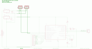
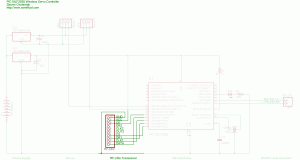
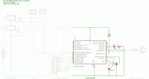
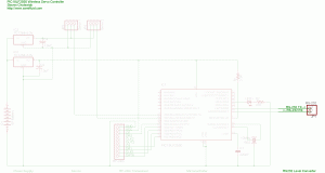
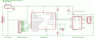
The source and firmware for the receiver circuit can be found at the bottom of the page. Each section of the circuit is labeled in the schematic. All of the sections and their components are described and discussed below. The part numbers for the components are linked to websites for data and more information when available.

Receiver Power Supply

The power supply uses a 9 volt battery and a TC1264-3.0V high-accuracy low-dropout linear voltage regulator to provide a stable 3 volt supply for the microcontroller and the transceiver. An additional TC1262-5.0V high-accuracy low-dropout linear voltage regulator is used to provide a stable 5 volt supply for the servos. 1uF (microFarad) polarized decoupling capacitors are necessary on the outputs of the voltage regulators to prevent spikes or ripples. A wall wart power supply as low as 5.3V can be substituted for the 9 Volt battery.

Receiver Servos

I used two standard hobby servos that were bought on eBay. Any servos that conform to the standard RC servo control scheme can be used with this circuit.

Receiver RF-24G Transceiver

The Laipac TRW-24G 2.4GHz transceiver uses a Nordic Semiconductor nRF2401a transceiver chip and includes all of the necessary components. The TRW-24G (also called the RF-24G and TXRX24G) requires a 3 Volt power supply and 3 Volt logic, so running the transceiver at 5 volts is not a viable option. Information on the chip’s interface cam be found in the following data sheets:
http://www.sparkfun.com/datasheets/RF/RF-24G_datasheet.pdf
http://www.sparkfun.com/datasheets/RF/RF-24G.pdf
http://www.sparkfun.com/datasheets/RF/nRF2401rev1_1.pdf
https://www.sparkfun.com/datasheets/RF/RF-24G.pdf

Receiver Microcontroller

The microcontroller used was a Microchip PIC18LF2550. I modified the PIC18F2550 Tiny PIC Bootloader assembly file so I could use a 10MHz crystal/resonator at 57,600 baud (the modified bootloader can be found at the bottom of the page). The PIC18LF2550 runs at a maximum speed of 16MHz (4 MIPs) with a 3 Volt power supply; however, I had 10MHz and 20MHz ceramic resonators on-hand, so I ran at the fastest ‘safe’ speed possible (I could overclock the PIC by running it at 20MHz with a 3 volt supply, but it would be running out of spec. so it may not operate reliably). The firmware was written in C (using CCS PICC) and can be found at the bottom of the page, in addition to a generic RF-24G driver for Laipac TRW-24G 2.4GHz transceivers. R1 is a pull-up resistor necessary for operation. C1 is a stabilizing capacitor that is used for the onboard USB voltage regulator (which is not utilized in this project). The component marked ‘RES’ is a 10MHz resonator. The LED connected to pin C4 is used to indicate data reception and can be omitted if necessary (although it is helpful for debugging).

Receiver RS232 Level Converter

The microcontroller USART pins need to be connected to a RS-232 Level Converter to connect to a PC for firmware updates using the Tiny PIC Bootloader. Otherwise, after initial programming they can be left disconnected.

Transmitter Circuit

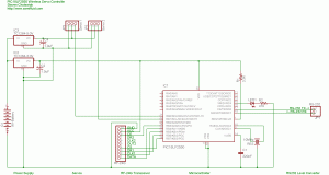
The circuit for the transmitter is exactly the same as the circuit for the 2.4GHz Serial Link; however, a custom firmware is used for the 2-byte payload of the RF-24G (1 byte for each servo). The firmware for the transmitter can be found below.

Source and Firmware

The PIC must initially programmed with the ‘SAC_tinybld18F2550_10MHz_57600’ hex file to program the bootloader on the PIC. Then, using Tiny PIC Bootloader, the hex files can be placed on the chips using the Tiny PIC Bootloader frontend with ’12h 34h 56h 78h 90h’ in the ‘List of codes to send first:’ in the ‘Options’ menu. Please feel free to contact me if you have any problems.
SAC_tinybld18F2550_10MHz_57600.asm (hex)
18LF2550 RF-24G Serial Servo Transmitter.c (hex)
18LF2550 RF-24G Serial Servo Receiver.c (hex)
RF-24G.c

Update – 02/28/2006

Here are two videos of my camera pan/tilt system under manual control: Manual Control. Here are two videos of my camera pan/tilt system under the control of a simple color tracking algorithm (which is configured to track the brightest red in the room): Color Tracking.
26 thoughts to “PIC18LF2550 Wireless Servo Controller”

  1. Hello,
    This is rajesh,
    http://www.semifluid.com/?p=25
    I need the clarification for the above said pic project,
    I have understude that the transmitter is controled through the pc computer RS232.
    But what i need is want to control it through joystich for pan and tilt function (POT)
    (Not with the computer rs232 controller).
    Please let me know how to do that with the manual joystich control and the compleate schematic diagram ???
    Awaiting for your favourable reply
    Thankyou/Regards
    Rajesh

  2. For manual joystick control using potentiometers, you would want to connect two potentiometers to two of the analog inputs, then read the values and transmit them at a regular interval. For example, you could change the main loop to:

    while(1) {

    if(INPUT(RF_24G_DR1)){

    getBuffer(); // Get packet
    printf(“%c%c%c”,101,buf[0],buf[1]);

    }

    // Get ADC Data
    set_adc_channel(0);
    delay_ms(1);
    buf[0] = READ_ADC();
    set_adc_channel(1);
    delay_ms(1);
    buf[1] = READ_ADC();

    // Transmit RF
    RF_24G_SetTx(); // switch to transmit
    delay_ms(1);
    putBuffer(); // send packet (buf)
    delay_ms(1); // won’t go back to recieve without this

    RF_24G_SetRx(); // switch back to receive
    delay_ms(1);

    }

  3. I could not understand that wher i should connect the two potentiometers
    for the pan and tilt Can you get me schematic for that ???
    Help me with the schematic diagram please.

  4. Rajesh, you need to connect one side of the potentiometers to +5V, the opposite sides to ground, and the wipers to A0 and A1 (with set_adc_channel(0) and set_adc_channel(1)). I don’t have a schematic available because I can’t breadboard the project to test it. However, this should be a straightforward connection:

    +5V
    |
    |
    /
    –A0 or A1
    /

    |
    |
    Ground

  5. hello sir
    I am trying to get the RC servo for this project but there are many different companies that make it. I would be highly obliged if you can send me the name and part number the servo that you have used. Please help me so that i waste no time is ordering the parts that i need for my project. Please do reply back.

    Kaushal Rana

  6. #5 (Kaushal) – The servo you need is dependent upon your application. I purchased a few Traxxas servos on eBay, but you may want high speed/high torque/small size for your application. I have been happy with mine, but you may want to look further into the servo specifications to make sure you buy the correct servo for your project.

  7. i am trying to program PIC 18lf2550 by using MPlab but it gives me lot of error. i dont know if i should use the C++ compiler or C compiler and some kind of called IDE Assembler because i have the access to these programe in my school please help me out. thankyou very much

  8. please reply we are trying to programme the PIC 18F2550 by using MP Lab software but it is giving me a lot of errors, please reply with some suggestions. thankyou very much.

  9. #7 & #8 (kaushal) – Sorry for the delay in my response, I am still catching up with a backlog of things that I’ve had to address. What kind of errors did you receive when trying to program the PIC using MPLAB? Are you loading the hex file using the File -> Import command? If not and if you are changing the C code, then you will need to have the CCS PCWH C compiler to recompile the code into a hex file. You may be able to port the code to another compiler if necessary. Let me know what kind of errors you are receiving and I’ll try to help fix things!

  10. Hi there! I am trying to build something similar to this but I’m not sure where to start. I need a low voltage, low profile, low range ( >50ft ), system to activate four separate electrically actuated pneumatic valves. I already have the valves figured out. But I am not sure how to trigger them wirelessly. I was curious if you had any ideas or if this was a no brainer for you.

    -Josh

  11. can i use this circuit for my project? i need to control an rc car. how can i replace it to bluetooth connection? using a bluetooth dongle?(USB) please help me…

  12. Hello!
    Great project!!
    what fuses do use?
    example:

    #include
    #fuses HSPLL…

    it is important to know how the fuses are configured for the program to work…

    Tanks

  13. there robotic design is very good . am a nigerian talented in making simple robot. please send me a six channel reciveir (vexploral).

  14. Hello Sir!!!

    I’m doing a wireless control webcam using servo motor and by interfacing with pc via wireless, but i’m facing problem in finding “wireless webcam” which i need to use, i’ll be very glad if u can advice me on this matter and is it possible to build a wireless webcam using normal USB interface webcam.tq.waiting ur propmt reply

    Regards
    Keshz

  15. To read a joystick you have to Read the two analog signals at first when it is at the center “Calibration”. Take like 20 samples average them. I if you have an EEprom save it there, every time the programs starts after it will skip the Calibration and load from EEprom the Calibration Value. Then every time you read the joysticks you minus the calibration values from the reading now you have a x & y axis with + & -. Now you need to plugin into a polar equation -Tan(Y/X)= angle “Direction it is facing” and also calculate magnitude Square root of (X^2 + Y^2) now you have your magnitude. It is like a vector now so you could write and if statment that says if magnitude is greater than the absolute value of 5 “threshold value” then calulate my angle and then Write if statments to detect angle ranges which correspond to direction of joystick then transmit a corresponding code over the air also the magnitude can be used for incremental steering or control.

    remember turn the joystick position into a vector

    Kerron Manwaring
    Specialk45@aol.com
    (914)-830-3542

  16. i m also trying this project as my final year project
    i am nt getting d nordic semiconductor module threrfor i used ordinary ask module bt i ma getting d problem in serial link

    i cnt able to establish wireless serial link between d computer & my microcontroller can any1 plz help me i stuck in this from last 4 month plz help me

    i am sending a data through d pc using the VB6.0 & microcontroller used is d 89S52 at receiving end how 2 make a serial link plzz help me

  17. Hi Steve,

    I came across your project in your web site.I am planning to do some modification
    in the code for which I wanted to Know Configuration bits you have used. is it possible for you
    to get the C Project you have used ? I need the .h header file so that I can view the Configuration Bits.

    http://www.semifluid.com/?p=25

    Thanks & Regards
    Senthil

  18. I just saw your wireless servo controller with a wireless camera attached and would like something like this for a project I’m working on. Could you let me know how to go about making or even buying something like this? Thanks!

  19. sir may i ask how to connect the servo motor on the camera and how to make system on vb6 because this system is our thesis the wireless camera using vb..sir it possible to make a system on vb trough this servo controller

  20. Hi I like this post and it was so fabulous and I am gonna bookmark it. One thing to say the Superb analysis you have done is trully remarkable.No one goes that extra mile these days? Well Done!!! Just one more suggestion you canget a Translator Application for your Global Readers .

  21. I need to build an external flat surface mounted wireless volume control using a belt drive around the OEM receiver’s volume control. Any suggestions are respected and appreciated.

    Thank You

  22. Hi all,
    I am trying to finish my project and looking for some one that can assemble a control board for me per the below requirements. I am sorry,I am a pure mechanical engineer and dont have much idea on these control boards, but know my requirements very well, so any help or lead will be appreciated.
    My requirements are as following. :
    for this project: I took 12V DC motors from a toy CAR that is capable of stearing at least two kids (about 165lb)….
    To control DC motor whose specs are,
    6V/12V supply voltage,
    15 to 30A power
    Need a micro chip controller that can,
    1, Reduce the speed of the motor from to 2rpm,
    2, Handling functions like CW AND CCW (clockwise and counter cwise)
    3, time based forward and revers motion: Soft start – CW for 2seconds – soft stop- pause1sec – soft start CCW for 2seconds – soft stop – number of cycles
    4, Alternatively proximity/touch sensor based CW and CCW (the board should be capable of giving the choice to select either sensor driven or time driven
    5, ON/OFF using remote.
    6, Number of cycles be relayed to any mobile phone.

    Please notice that we need at least one assembly board that can be readily used

Leave a Reply

This site uses Akismet to reduce spam. Learn how your comment data is processed.