 Having a 2.4GHz Serial Link is helpful, but what kind of applications could it be utilized for? Well, I had a number of 1-axis accelerometers from Freescale (graciously provided by their samples department for my electronics lab projects), which I could use detect object orientation. Making the accelerometers wireless would allow for remote sensing of object orientation, which could be applied to virtual reality or possibly augmented cognition. In any case, it allows for some fun experimentation!
Transmitter Circuit
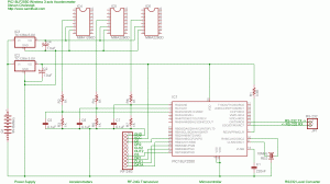
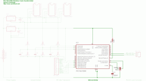
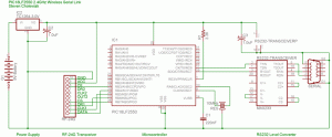
The source and firmware for the transmitter circuit can be found at the bottom of the page. Each section of the circuit is labeled in the schematic. All of the sections and their components are described and discussed below. The part numbers for the components are linked to websites for data and more information when available.
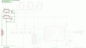
Transmitter Power Supply
The power supply uses a 9 volt battery and a TC1264-3.0V high-accuracy low-dropout linear voltage regulator to provide a stable 3 volt supply for the microcontroller and the transceiver. An additional TC1262-5.0V high-accuracy low-dropout linear voltage regulator is used to provide a stable 5 volt supply for the accelerometers. 1uF (microFarad) polarized decoupling capacitors are necessary on the outputs of the voltage regulators to prevent spikes or ripples. A wall wart power supply as low as 5.3V can be substituted for the 9 Volt battery.
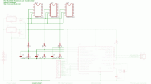
Transmitter Accelerometers
To sense the position of the board, I used 3 single axis accelerometers in an X-Y-Z configuration. I used two MMA2260D Low-G X-axis accelerometers and one MMA1260D Low-G Z-axis accelerometer. The two X-axis accelerometers were positioned in an X-Y configuration and the Z-axis accelerometer was used to sense gravity in the Z-direction. The resistors below the accelerometers are used as a voltage divider so that the PIC, which is running at 3V, can read the voltage, which will vary from 0V to 2.5V. With this configuration, for each accelerometer 1.85V is +1G, 1.25V is 0G, and 0.65V is -1G.
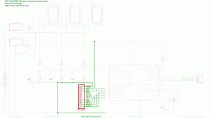
Transmitter RF-24G Transceiver
The Laipac TRW-24G 2.4GHz transceiver uses a Nordic Semiconductor nRF2401a transceiver chip and includes all of the necessary components. The TRW-24G (also called the RF-24G and TXRX24G) requires a 3 Volt power supply and 3 Volt logic, so running the transceiver at 5 volts is not a viable option. Information on the chip’s interface cam be found in the following data sheets:
– http://www.sparkfun.com/datasheets/RF/RF-24G_datasheet.pdf
– http://www.sparkfun.com/datasheets/RF/RF-24G.pdf
– http://www.sparkfun.com/datasheets/RF/nRF2401rev1_1.pdf
Transmitter Microcontroller
The microcontroller used was a Microchip PIC18LF2550. I modified the PIC18F2550 Tiny PIC Bootloader assembly file so I could use a 10MHz crystal/resonator at 57,600 baud (the modified bootloader can be found at the bottom of the page). The PIC18LF2550 runs at a maximum speed of 16MHz (4 MIPs) with a 3 Volt power supply; however, I had 10MHz and 20MHz ceramic resonators on-hand, so I ran at the fastest ‘safe’ speed possible (I could overclock the PIC by running it at 20MHz with a 3 volt supply, but it would be running out of spec. so it may not operate reliably). The firmware was written in C (using CCS PICC) and can be found at the bottom of the page, in addition to a generic RF-24G driver for Laipac TRW-24G 2.4GHz transceivers. R1 is a pull-up resistor necessary for operation. C1 is a stabilizing capacitor that is used for the onboard USB voltage regulator (which is not utilized in this project). The component marked ‘RES’ is a 10MHz resonator.
Transmitter RS232 Level Converter
The microcontroller USART pins need to be connected to a RS-232 Level Converter to connect to a PC for firmware updates using the Tiny PIC Bootloader. Otherwise, after initial programming they can be left disconnected.
Receiver Circuit
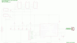
The circuit for the receiver is exactly the same as the circuit for the 2.4GHz Serial Link; however, the receiver code is different because it expects a 6-byte payload from the RF-24G. The source code for the receiver can be found below.
Source and Firmware
The PIC must initially programmed with the ‘SAC_tinybld18F2550_10MHz_57600’ hex file to program the bootloader on the PIC. Then, using Tiny PIC Bootloader, the hex files can be placed on the chips using the Tiny PIC Bootloader frontend with ’12h 34h 56h 78h 90h’ in the ‘List of codes to send first:’ in the ‘Options’ menu.
– SAC_tinybld18F2550_10MHz_57600.asm (hex)
– 18LF2550 RF-24G Accelerometer Transmitter.c (hex)
– 18LF2550 RF-24G Accelerometer Receiver.c (hex)
– RF-24G_6-byte.c
